 Русский
Graphite Hot Zone is the King, but Metal Hot Zone is the Queen
Throughout the last few decades, the heat-treating industry has experienced a significant shift in the type of hot zone material that is most commonly used in vacuum furnaces. In the 1970s, almost 90% of the hot zones installed were all-metal. However today, about 80% are made from graphite.
Graphite insulation has improved significantly over the past several decades with respect to thermal stability and product integrity over a wide temperature and application range. Therefore, it is now significantly more cost effective, more forgiving to operation mistakes and energy saving than an all metal hot zone.
If enough care is taken a graphite hot zone will produce acceptable results for most vacuum processing applications.
Still, all-metal hot zone has maintained its use case in sensitive processes like diffusion bonding and aluminum brazing.
Benefits of using all metal hot zone include a better leak rate, higher ultimate vacuum levels, improved pump down capabilities, a cleaner working environment, faster gas quenching and a lower probability of contaminated parts.
Drawbacks of all metal hot zones are mainly much higher cost in acquisition and operation.
Thermal Heating and Insulation Basics
To understand the differences between hot zones material and therefore the optimal use case for all-metal and all-graphite hot zones, we need to take a step back and understand heat transfer principles.
There are three modes of heat transfer, namely radiation, conduction and convection. To do its job the vacuum hot zone must deal with all of them.
In simplest terms, radiation is responsible to heating the surface of the work-piece and conduction is responsible of heat penetration from work-piece surface to the center of the work-piece. Convection may or may not play a role inside a vacuum furnace.
- Inside the vacuum furnace the main heat transfer method is radiation or radiant heat. Without it the work-piece will not be able to heat. Radiant heat is excess energy of an atom that is being released in form of an electro-magnetic wave. The electro-magentic wave will be emitted by the heater inside the hot zone travel till until it is absorbed by something in its path. Hopefully a work-piece that is intended to be heated. That is the method used by our sun to deliver heat to us. The radiant heat does not require a medium or intermediate material to transfer the heat. In fact, a vacuum is the optimal condition for transferring radiant heat since in a vacuum there is no gas in the way to scatter or absorb it. As a result, while radiant heat is needed to heat up the work-pieces, at the same time the insulating system in a vacuum furnace must be specifically designed to reduce radiant heat absorption.
- As a work-piece absorbs radiant heat on the surface, then conduction or conductive heat transfer towards the core of the work piece occurs by direct molecular collision. On a microscopic scale, the kinetic energy of molecules vary in direct proportion to their temperature. So, as the temperature rises the molecules increase their motion and gain kinetic energy. They then collide with cooler molecules, transferring their kinetic energy and hence their heat. That means a direct contact of hot and cold parts is needed for conduction to work. So a hot zone designed that minimizes conduction transmission paths from inside of the hot zone to the outside will have great insulation effect in terms of preventing the heat leaving the hot zone through conduction.
- The final heat transfer method is convection that occurs when “fast” gas molecules float in space and hit other molecules. Think “steam” coming out when the water is boiled. Hot zone must be designed with convection heat transfer in mind, though, as long as the chamber is under vacuum during operation, this mode of heat transfer is practically non-existent, as convection requires the presence of gas molecules to transfer heat energy, but there are few molecules present in the evacuated chamber.
For convection heating to work, the hot zone needs to be back-filled up with gas (typically nitrogen or argon) and a fan to circulate heat to all parts in the charge (work-pieces). Unlike radiant heating, parts do not have to be in the direct sight line of the heating elements to feel the effects, resulting in better uniformity of heating.
Thus convection heating does play in the vacuum furnace a role to improve heat up rate and temperature uniformity below 850 °C, as radiant heat transfer method is less effective at lower temperatures.
Another instance where convection heating plays a role is when partial pressure is used (here also gas is back-filled into the hot zone during operation), for example, to prevent vaporization of elements present in the parts (such as chromium in stainless steels). Convection also plays a significant role during high-pressure gas quenching.
Thus, a well designed hot zone will have flapper nozzles to let the gas, used for convection heating, in and trap it inside for hot zone while circulating it around the charge (work-pieces) to reach more “hidden” areas of the work-pieces. That will make the heating much more energy efficient and prevent heating losses by not allowing hot gas to leave the hot zone. At the same time during the gas quench the flapper nozzles will open to let the quench gas circulate into and out of the hot zone while it makes its passes through a heat exchanger to cool down.
Since, the heat transfer aspects inside the vacuum hot zone are now understood, let’s look at insulation aspects.
There are several insulating designs common to vacuum furnaces:
- All metal hot zone design
- All graphite hot zone design
- Composite designs using both metal and graphite or ceramic insulation
All Metal Hot Zone Construction
All-metal hot zones are constructed from metallic shields consisting of molybdenum and stainless steel with air gaps (or perhaps more accurately a vacuum gap) between them to retard the transfer of radiant energy.
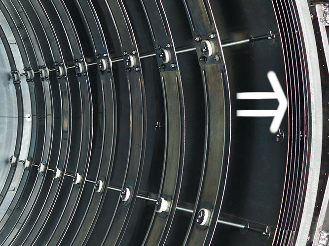
The number of heat shields and their materials of construction is a function of the temperature rating of the furnace (See Figure 1). Each shield has an additive insulating effect. It is common for the system to incorporate a total of five or six shields, two or more layers of molybdenum on the hot face, followed by several layers of type 304 or 316 stainless steel.
Molybdenum has a superior (five times lower) emissivity and much higher heat resistance than stainless steel. This reduced emissivity allows it to reflect more of the radiant heat and absorb less. Thus, the key is that the heat shield is reflecting the radiant heat back into the work-pieces and passes on only a small amount of radiant heat to the next shield layer. Therefore, two layers of molybdenum are normally sufficient to reduce the temperature sufficiently, so that stainless steel shields can be used on following layers of the hot zone that are getting closer to the water cooled wall of vacuum vessel.
The drawback of molybdenum is that embrittled (aka recrystallized) heat shields will readily fracture along the grain boundaries when impact loaded and are susceptible to damage in an industrial setting, so extreme care must be taken when inspecting or performing maintenance on an all-metal hot zone.
The Importance of Emissivity
All-metal insulating system depends heavily on its ability to reflect radiant heat. Emissivity defines the proportion of radiant energy a material, such as a metal reflector, absorbs versus how much it reflects. So the material should be selected with low emissivity and it should be maintained over time.
However, the material ability to reflect heat depends on the material itself, the wavelength of the radiant heat, which is itself dictated by its temperature and oxidation level.
Temperature inside a vacuum hot zone is a supporting factor as it helps to further reduce emissivity value, however oxidation is what needs to be controlled for during operation.
Contamination of All Metal Insulating System
Molybdenum has a 0.13 emissivity value at 950 °C and slightly better at higher temperature (meaning it only absorbs 13% of radiation heat and reflects the rest), while Type 316 polished steel has 0.66 and oxidized steel will be close to 0.9 emissivity value.
Therefore, the principal issue with all-metal insulating systems is the loss of emissivity due to contamination of the metal heat shields. This can be due to air leaking into the chamber, oxygen / water vapor present in the inert gas backfill lines, or to contaminated backfill gas. Backfill lines, regulators, valves, and other components undergo considerable operational stress during repeated quench and reheat cycles.
Although the equipment is tight when brand new, after years of repeated cycling the seals and threaded connections start to leak, components begin to fail, and soft solder joints can experience cracking. This allows air to leak into the chamber and causes surface oxidation and dulling of the heat shields and furnace interior.
The result of air infiltration is a reduction in the reflectiveness of the shields, and since they insulate by reflecting radiant heat, this dulling process drastically reduces insulation effectiveness of an all-metal insulating system.
One of the ways to detect this (other than visually) is to monitor power usage, which will increase as the thermal efficiency of the hot zone deteriorates. At some point, the furnace, which may have originally only required 50 – 60% of the installed power, has a difficult time reaching temperature even at 90 – 100% input.
In addition to gradual contamination caused by air leaks, the heat shielding can be oxidized in the event of a mishap, such as opening the furnace door at elevated temperature or the failure of a component which allows air entry. Oxygen-laden air enters quickly and contaminates the heat shields. This can be severe enough to render the furnace unusable, despite attempts to run hydrogen clean-up cycles, forcing the shielding to be replaced.
Another way heat shielding can change emissivity is from the release of contaminants from the charge (work-pieces), such as oils, greases, binders, brazing pastes and other outgassed products, which accumulate over time to render the shielding ineffective. To prevent this, care must be taken to properly clean the work-pieces before they enter the vacuum furnace.
Still another source of heat shielding contamination is moisture from the factory during loading and unloading of the furnace, or if the furnace is turned off and the left open when not in operation. If the dew point of the air is below the temperature of the cold wall, condensation will occur, depositing moisture, which will release its oxygen under vacuum, and cause oxidation of the heat shielding.
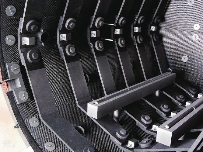
Graphite Hot Zone Construction
A popular alternative to all metal lined hot zones utilizes graphite-based insulation. A typical design for a maximum operating temperature of 1400 ºC consists of a 50 mm thick graphite material, typically in the form of (felt) blanket or board. It is not uncommon to have two or more layers of material.
In addition, the outer shell of the furnace is typically water-cooled and the fact that most processes run either under vacuum or in a partial pressure atmosphere further reduces heat transfer.
The graphite blanket or board is usually installed in layers, and during installation, the layers are staggered to minimize the likelihood of continuous gaps from inside to outside and subsequent heat loss.
Blanket products can subsequently be covered by a graphite paint, and graphite board products can be supplied with a hot face covering of graphite foil or foil-bonded carbon composite (CFC). These improve reflectivity (i.e., reduced emissivity) of the heat from the graphite heaters back toward the charge (work-pieces) as well as protect the surface from damage by process or quench gases.
There can also be intermediate layers of foil sandwiched between the layers of graphite boards. These additional foil layers provide increased insulating efficiency.
In a graphite insulation system, the graphite blanket / board has a low thermal conductivity, which resists heat transfer from the hot side to the cool side.
With a thermal conductivity three times better (lower) than metal heat shielding, these systems provide superior insulating characteristics in comparison to all-metal hot zones and are normally less expensive and take less time to install.
Various graphite insulation layers work by blocking the radiant heat emitted from the interior of the hot zone, which minimizes the heat transfer to the cage supporting the insulation and ultimately to the cold wall.
Because of graphite’s low conductivity, these hot zones are typically more energy-efficient than all-metal designs.
One of the disadvantages of graphite materials is that they have a high specific heat (cp), a property that defines how much thermal energy a material can hold. Compared to molybdenum, a common metallic heat shielding, graphite’s specific heat is more than double. Therefore, a given weight of graphite will retain twice the heat energy as molybdenum.
This results in a slightly reduced quenching capability because some of the cooling capacity of the quenching gas is needed to bring down the insulation temperature.
In addition to the thermal mass of the insulation containing excess heat, graphite is also (by design) a poor conductor, so its heat is trapped within the graphite fibers, delaying the release of its heat energy during quenching.
The multiple separated layers of heat shielding used in the all-metal insulation design, on the other hand, allow the quench gas to freely flow between them, allowing for more rapid quenching.
Gas Erosion
When considering graphite insulation one must be aware of the potential for erosion of the material due to abrasion from the quenching gas. This problem is most often observed in the pressure range of 6 – 20 bar along the exposed joints and penetrations through the boards when rapid gas quenching. For this reason, many of these areas are capped or covered by another material such as molybdenum or carbon composite. At a pressure of 20 bar, a quenching gas such as nitrogen has a weight of 51 kg/m3, so it’s easy to understand how high-velocity gas quenching can so easily erode the graphite board.
In addition to the reduction in insulating efficiency due to loss of insulation thickness, the other problem resulting from gas erosion is the fine graphite powder that results. This powder will be carried by the quenching gas through the heat exchanger and blower of the gas quench system. It then collects inside the heat exchanger fins, decreasing its efficiency. In addition, the graphite powder can contaminate the work and interfere with the process being performed in the furnace.
De-Binding
In addition to erosion from the quenching gas, another source of fugitive graphite powder is vaporization of the binder from the board (aka de-binding). Without the binder, the graphite is liberated as a fine powder that can contaminate the process and clog the quench gas cooling system, in the same way, the abraded powder can.
Graphite Decomposition When Exposed to Oxygen
A major concern with the use of graphite insulation is the potential for it to decompose when exposed to air. If oxygen is present at temperatures above approximately 300°C, the carbon that makes up the graphite will combine with oxygen to form CO and CO2.
(1) C + ½O2 = CO and C + O2 = CO2
The result is that the graphite will slowly turn into CO and CO2 gas, which will be removed from the furnace by the pumping system. At first, small pits will occur, often observed as a “sugar cube” surface appearance and as further decomposition ensues, the graphite continues to lose mass and simply disappears.
Conclusions
A majority of today’s vacuum heat-treating furnaces are supplied with graphite hot zones given the tremendous versatility of this material choice.
Graphite insulation has improved significantly over the past several decades with respect to thermal stability and product integrity over a wide temperature and application range.
Just as with all metal-lined vacuum furnaces, a leak-tight vacuum furnace system ensures that air (oxygen) and water vapor are kept out of the hot zone.
Clean, dry work-pieces entering the furnace extends the overall life of all hot zone materials.
As a result, a graphite hot zone will work for the majority of heat treatment requirements, but still select a metal hot zone if:
- The process cannot tolerate incidental dust or dirt. These sensitive processes include diffusion bonding and aluminum brazing.
- The process cycle requires high temperatures and ramp rates of more than 30 °C per minute.
- The process cycle requires very high temperature uniformity range of around +/- 3 °C
Also consider how materials might react with carbons in a graphite furnace. Graphite dust lowers melting temperatures and can have an adverse effect – even eutectic reactions – on certain materials.
In the above cases, an all-metal hot zone would be the best choice to ensure optimal results.