 Русский
Purpose of Multi Chamber Vacuum Furnaces
In cases where a single chamber vacuum furnace can not fulfill heat treatment requirements either from productivity or quench ability point of view, then a multi chamber furnaces should be considered.
Multi chamber means the heating will be done in one chamber and quenching in a different chamber. An additional transfer chamber can be added between heating and quenching chamber to either isolate the heating chamber from huge pressure inside gas quench chamber or avoid pollution of the oil from the oil quench chamber. Let’s illustrate the three chamber models below:


However, the absolute bestseller is a double chamber vacuum furnace with oil quenching system that offers an excellent solution for a wide range of heat treatment processes and applications. That we will introduce in more detail below.
Double Chamber Vacuum Furnace with Oil Quench Introduction
The double chamber vacuum furnace is offered in configuration with two sets of fine vacuum pumping groups (one set for each chamber), complete with rotary vane pump and roots pump.
The charge (work-pieces) is heated in a hot zone of circular section, with graphite insulation and graphite heating elements arranged in rings around the working volume.
Optionally a square graphite hot zone can be offered as per user requirements.
The hot zone can operate in vacuum up to 1250 °C Degrees.
At lower temperatures below 850 °C, when the heat transfer by radiation is less effective, heating can also be carried out in inert gas, with forced circulation.
After heating, the charge (work-pieces) is automatically transferred into the pre-evacuated quenching module, where the cooling can be done in vacuum, with static inert gas or rapidly immersed into an oil tank for very fast cooling result.
The heating chamber and the quenching module are separated by an isolation door.
The multi chamber vacuum furnace is a versatile system, that operates with high temperature uniformity, allows fast quenching of the charges (work-pieces) and guarantees high quality and repeatable heat treatments.
Vacuum Oil Quench Furnace Structural Design
Heating Chamber
The heating chamber consists of the following components:
- Vacuum vessel
- Hot zone

The double skinned, water cooled, vacuum vessel separates the outside environment from the interior containing the hot zone.
It is a cylindrical chamber horizontally mounted and welded on four support feet. The vessel has a dished end (rear/maintenance door) and a flange for its connection to the quenching module, through a vertically mounted isolation valve. The rear/maintenance door is manually operated and electrically locked to the cylindrical vessel by a multi-claw mechanism, whereas the isolation valve is automatic and operated by a pneumatic actuator.
The vacuum chamber is provided with a number of flanges for the connection to the vacuum and partial pressure system, to the power supply system and to the temperature, vacuum & pressure sensors.
All joints are ”o”-ring sealed and are suitable for operations under high vacuum and elevated temperatures.
The maximum permitted cooling water pressure of the water jacket is controlled by safety valves.
The vacuum chamber is in carbon steel and a special anti-corrosion and temperature resistant paint is applied to the inner surface of the chamber. Optionally, the material of the vacuum chamber can be upgraded to stainless steel upon request.
The legs of the chamber are on lockable rollers that allow its movement for maintenance operations.
The hot zone provides the thermally insulated volume – within the vacuum vessel – where the charge is heated up for the programmed thermal process. It has a circular section and it consists of a horizontally mounted carbon steel frame that supports the insulation panels, the heating elements and the hearth for the charge (work-pieces).
The rigid graphite board panels provide a low mass thermal insulation pack that drastically reduces the amount of heat losses.
The panels are fixed to the structure by molybdenum pins. The rigid graphite of the insulating system is covered by carbon fiber (CFC) layer for maximum durability and extended service life of the hot zone.

The rear door of the hot zone is directly hinged to the thermic chamber. It is opened and closed independently from the door of the vacuum chamber and can therefore guarantee the required tightness, for improved temperature uniformity within the work zone, and for reduced heat losses.
The isolating door between heating chamber and quenching module is complete with an insulation board, which is pressed against the hot zone body when the door is vertically closed. The heating system consists of a set of six rings, made of wide band graphite rigid elements. The rings are connected in parallel in couples, and the resulting elements are arranged in a delta configuration.
A gas circulation fan driven by a water cooled electric motor is installed on the front door of the hot zone.
The hearth is made of high-grade isostatic graphite profiles. Molybdenum rods are mounted on the graphite supports to avoid the direct contact between graphite and steel at high temperature. The hot zone is easily accessible for the maintenance activities on the heating elements and on the thermal insulation.
Power Feed Through
Electric power is supplied to the heating elements through water cooled copper rods, assembled and sealed to the vacuum chamber.
The cooling water flow is continuously measured by digital flow meters that transmit the reading to the PLC to protect the system in case of lack of water.
Convective Heating and Gas Circulation Fan
Convective heating is used to improve the heat transfer at low temperatures, when transfer by radiation in vacuum is less effective.
Protective gas is injected into the vacuum chamber after it has been evacuated to the required set value.
A gas circulation fan is installed on the front of the hot zone. The fan and its shaft are in CFC – Carbon Fiber Composite material.
The fan is driven by a water-cooled asynchronous electric motor installed on the front door of the hot zone.
Convective heating provides both faster heating and improved temperature uniformity within the working volume.
Quenching / Cooling Chamber
The quenching module consists of the following components:
- Gas quenching chamber
- Oil tank
- Lifting table
- Telescopic load transferring fork
The gas quenching chamber is a single-layer carbon steel vessel with rectangular section designed and manufactured to operate under vacuum and above atmospheric pressure (up to 1.5 bar abs.). The chamber is reinforced with stiffeners and it is water cooled. It is provided with a pneumatically operated lift door (front loading & unloading door) and it is connected to the heating chamber via the isolation valve.
A fan is installed at the top of the quenching chamber to circulate nitrogen when the charge (work-pieces) is cooled in gas. The fan is connected to a three-phase asynchronous motor and its rotating speed is controlled via a variable frequency inverter.
The gas quenching chamber is installed directly on top of an oil tank. This is a single-layer carbon steel structure of rectangular section, insulated by 50 mm aluminium silicate detachable panels. A set of steel I-beams under the shell function as load-bearing structural elements. The oil tank can be directly placed on the factory floor.

Before quenching, the oil in the tank can be preheated by the heating control system that guarantees suitable oil temperature for the specific heat treatment process.
The tank is provided with two high efficiency – variable pitch – axial flow fan wheels (super-quench agitators) and with an oil stream distribution guiding structure. This configuration guarantees the optimal stirring effect on the oil, a high velocity flow of the oil through the charge (work-pieces) and therefore a fast and uniform removal of heat from the charge (work-pieces). The rotating direction and speed of the agitators are controlled by variable frequency controllers, for a fine regulation of the quenching rate.
The motor of the agitators can operate under vacuum and under pressure, therefore they do not require dynamic seals and this avoids leakages and failures of the system.
The quenching oil is cooled by a system with high temperature resistant pump and heat exchanger. The pump circulates the oil from the tank through the heat exchanger and back into the tank. The heat exchanger is dimensioned to reduce the oil temperature within a suitable time interval. The heat exchanger can be air or water called as per user request.
The charge (work-pieces) is lowered into the oil tank with an electrically operated lifting table. This moves along two vertical guides of the lifting system driven by gear motor and connected with chains. The motor speed is controlled with a variable frequency inverter and this allows to regulate to the specific application the velocity at which the table enters the oil. The motor is installed outside of the quenching chamber and a chain tension adjuster on the lifting table allows regulations to be carried out without draining the quenching oil.
The charge (work-pieces) is transferred between the heating chamber and the quenching module by a telescopic fork, installed on the lifting table. The fork is driven by a geared motor, installed outside of the quenching chamber. No actuator is inside the chamber and therefore any maintenance operation can be carried out without draining the quenching oil.
Vacuum and Partial Pressure System
The vacuum system is designed to achieve the vacuum requirements and may look different depending on volume of the vacuum chamber. Each chamber is connected to its own pumping group. For illustrative purposes it would consist of the following components and features:
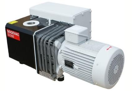
Rotary Vane Pump (s) – Leybold Sogevac 300B, for heating chamber and separate pump for cooling chamber.

Roots Pump(s) – Leybold WAU2001 for the heating chamber and WAU1001 for the cooling chamber.
Valves are pneumatically activated and motion controlled by limit switches.
Over-pressure safety valves are installed.
Leak detection port on the vacuum piping, for convenient maintenance operations and leak detection is available.
Vacuum gauge – the vacuum chamber is provided with a Pirani gauge. Vacuum levels are digitally displayed on the HMI.
The rotary vane pump and the Roots pump are isolated from the piping system by bellows-type flexible couplings. These connectors minimize vibrations from reaching the furnace chamber.
Optionally a protective gas injection system allows to heat up the charge (work-pieces) under partial pressure, to prevent vaporization of volatile elements (chromium, etc.) from the work-piece. A needle valve bleeds – at a set throughput – protective gas into the heating chamber and the required partial pressure is regulated and maintained by the control system.
The over-pressure protection is installed between the furnace and vacuum pumps. The vacuum system is interlocked to provide for safe operating conditions. The control system interlocks are designed to “fail-safe” in case of an electrical power failure.
Optional Low Pressure Carburizing LPC / CN Module
Low pressure carburizing (LPC/CN module) allows the furnace to carry out carburizing & carbonitriding processes. The module includes a gas supply system, complete with a mass-flow controller, a pressure transducer, piping & valves, and a filter on the pumping group.
The supply system is designed to optimize the distribution of the process gas within the work volume and to minimize the deposition of soot around the gas inlet nozzle and the risk of its obstruction.
The mass-flow controller guarantees that an accurate and correct amount of process gas is supplied into the work zone.
A by-pass with valve is added to the pumping group to allow a continuous control of the pressure inside the vacuum chamber.


A fine regulation of the correct amount of process gas in the work volume is necessary for the success of the carburizing cycle.
A filter protects the vacuum pumps from soot and from particles as little as 5 microns, preventing scratches to the casings and deterioration of the sealing oils.
Furthermore, the hot gas mixture inside the furnace is cooled down before it reaches the pumps.
Nitrogen is inserted in the exhaust line, to dilute the partial pressure of acetylene to a suitable value.
Acetylene Carburizing Expert control program supervises the correct parameters for the cycle and it provides the operator with an interface to monitor the status of the system. In addition, the system includes a mathematical model that allows simulation of the processes and can be used by the operator to define the cycle parameters most suitable for the specific steel and for the required depth of the carburized layer. The acetylene carburizing expert software is integrated in the furnace overall control system and human machine interface (HMI).
The low pressure carburizing (LPC) module guarantees accurate processes and high repeatability of the cycles.
Cooling Water Distribution System
A cooling water distribution system assures adequate cooling of all furnace components. It is split into two independent loops:
- Circulation Loop 1: basic flow. This loop provides the amount of cooling water required for the operation during heating. Cooling water is distributed to the vacuum chamber, to the pumping group, to the current feed-through, etc. This circuit includes a high-pressure supply manifold and a return manifold, both in stainless steel. Flow interlock switches are installed on all critical return lines and ball valves on supply lines. The status of the interlocked circuits is displayed on the operator’s control panel.
- Circulation Loop 2: quenching flow. This loop provides the additional amount of cooling water required during the quenching of the charge (work-pieces) inside the oil tank. Water is supplied to the heat exchanger through an independent inlet manifold. This loop also includes a return manifold independent form the circulation loop 1, for the basic flow.
Non-ferrous pipe fittings, and non-metallic hoses are used for all cooling circuits.
Automatic valves are provided to switch to emergency water supply upon loss of electricity.
Electric Power and Process Control Enclosure
The power and control instrumentation are housed inside a freestanding power distribution and process control enclosure.
Inside the electric cabinet, motor starters and circuit breakers are installed for the electrical motors. Circuit breaker disconnects are installed for other circuits. Lockable disconnects on the face of the cabinet, or strategically placed lockable local disconnects, are provided for maintenance to minimize downtime but ensure safety.
The power distribution and process control enclosure has a single electrical power connection and provides power to the furnace components. The cable can be lead in the cabinet from top or bottom, depends on customer’s requirement.
The cabinet houses the following instrumentation and components:
- PLC Siemens
- Industrial PC, with 19” HMI
- Eurotherm temperature controller
- Eurotherm over-temperature protection instrument
- Main switch breaker
- Power meter
- Analogue ammeters to measure the current in the heating elements.
- UPS – uninterrupted power supply
- Andon light (green, yellow & red)
- Acoustic alarm device
- Set of internal safety lights
- Fresh air intake fan
The heating power supplied to the heating elements is controlled through a thyristor.
Temperature Sensors
Two S-type Pt-PtRh thermocouples are installed on the heating chamber, one for temperature control and record, and one for over-temperature protection. SAT thermocouples can be inserted for temperature calibration, when needed.
Two J-type Fe-CuNi thermocouples are installed in the oil quenching tank.
Safeties and Protections
The furnace is designed and manufactured in compliance with the relevant health and safety standards. The furnace control system is designed with safety interlocks that protect the equipment operators from injury and that
prevent damage to the furnace equipment during normal operation of the furnace.
The interlock and safeties include, among others:
- In case of failure of a control thermocouple, the PLC stops the heating and provides an alarm.
- In case of over-temperature within the hot zone, the over-temperature instrument stops the heating and the system provides an alarm.
- In case of lack of electrical power, the vacuum valve shuts down to a safe position.
- In case of lack of cooling water flow within the distribution system, the PLC stops the heating of the furnace and an alarm is provided.
The furnace door can only be opened when the pressure inside the vacuum chamber is balanced to the atmospheric pressure.