 Русский
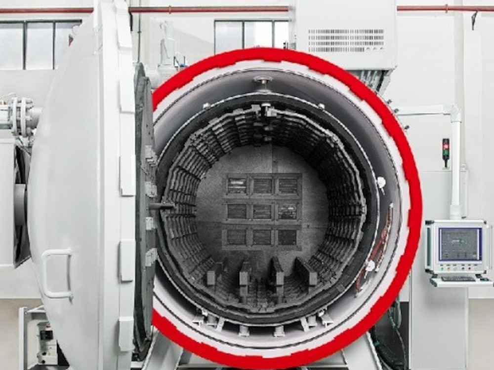
Vacuum Furnace Overview
Our premium best selling single chamber vacuum furnace is a cold wall heat treatment furnace that offers an excellent solution for a wide range of heat treatment processes and applications, including brazing, hardening, annealing, ageing, tempering, etc.
The furnace is offered in a configuration with a high vacuum pumping group, complete with rotary vane pump, roots pump and oil diffusion pump. Of course it can also come supplied with fine vacuum pumping group on request.
The vacuum furnace is offered with round graphite hot zone per default, however of a metal and square shape are also available on request.
The furnace can operate in vacuum up to a maximum temperature of 1400 °C.
At lower temperatures, when the heat transfer by radiation is less effective, heating can also be carried out in protective gas, with forced circulation, up to 850 °C.
Quenching can be carried out in vacuum, in static inert gas and in pressurized inert gas (up to 20 bar) with forced circulation.
The single chamber vacuum furnace is a versatile system, that operates with high temperature uniformity and guarantees high quality and repeatable heat treatment result.
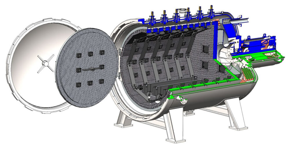
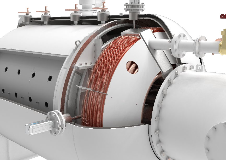
Vacuum Furnace Structural Design
Vacuum Vessel
The double skinned, water cooled vacuum vessel separates the outside environment from the interior containing the hot zone and the heat exchanger and fan assembly.
The chamber is a cylindrical vessel with dished ends at the front and at the rear. It is horizontally mounted and welded on four support feet, so it can be placed on the factory floor. Rails for a loading cart are located in between the legs.
The vacuum vessel is provided with a number of flanges for the connection of the vacuum system, the power supply system, the gas quenching system, the temperature, vacuum & pressure sensors and the safety valve.
A flange on the rear of the vessel supports the large gas quenching motor. The flange allows for easy dismounting of the gas circulation fan.
All joints are ”o”-ring sealed and are suitable for operations under high vacuum and elevated temperatures.
The maximum permitted cooling water pressure of the water jacket is controlled by safety valves.
The front door is locked to the chamber flange with a bayonet closure mechanism. The door rotation is driven by an electrical actuator and a pin system that prevents the door from rotating during operations under vacuum or above atmospheric pressure.
The vacuum chamber is in carbon steel and a special anti-corrosion and temperature resistant paint is applied to the inner surface of the chamber. Optionally, the material of the vacuum chamber can be upgraded to stainless steel upon request.
The vessel is designed and manufactured in compliance with the relevant pressure equipment regulations.
Vacuum and Partial Pressure System
The vacuum system is designed to achieve the vacuum requirements and may look different depending on volume of the vacuum chamber and desired vacuum level. In case of high vacuum system it may consist of the following components and features for illustrative purpose:
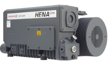
Rotary Vane Pump (s) – Pfeiffer Hena 302
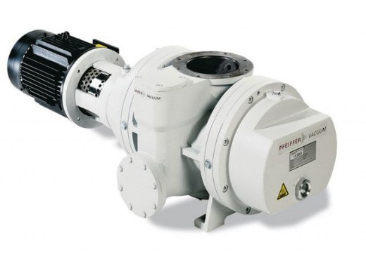
Roots Pump(s) – Pfeiffer Okta 2000
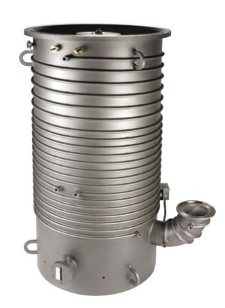
Oil Diffusion Pump – Agilent NHS35
The pump is connected to the vacuum chamber flange with a pneumatically driven high vacuum poppet valve that operates in the vertical position.
The pump is provided with a thermocouple to monitor the oil temperature, to indicate when it’s ready for operation.
Holding pump is attached to the high vacuum pump discharge line (fore line) to hold vacuum on the high vacuum pump during initial start-up (pump down) and standby periods. The holding pump is mounted on a small elevated platform to facilitate oil changes.
Valves are pneumatically activated and motion controlled by limit switches.
Over-pressure safety valves are installed.
Leak detection port on the vacuum piping, for convenient maintenance operations and leak detection is available.
Vacuum gauge – the vacuum chamber is provided with a Pirani gauge. Vacuum levels are digitally displayed on the Human Machine Interface (HMI).
The rotary vane pump and the roots pump are isolated from the piping system by bellows-type flexible couplings. These connectors minimize vibrations from reaching the furnace chamber.
Optionally a protective gas injection system allows to heat up the charge (work-pieces) under partial pressure, to prevent vaporization of volatile elements (chromium, etc.) from the work-piece. A needle valve bleeds – at a set throughput – protective gas into the heating chamber and the required partial pressure is regulated and maintained by the control system.
The over-pressure protection is installed between the furnace and vacuum pumps. The vacuum system is interlocked to provide for safe operating conditions. The control system interlocks are designed to “fail-safe” in case of an electrical power failure.
Hot Zone
The hot zone provides thermally insulated volume, within the vacuum chamber, where the charge is heated up for the programmed thermal process. It has a circular section and it consists of a horizontally mounted
carbon steel frame that supports the insulation panels, the heating elements and the hearth for the charge (work-pieces). The rigid graphite board panels provide a mass thermal insulation pack that drastically reduces the amount of heat losses. The panels are fixed to the structure by molybdenum pins.
The rigid graphite of the insulating system is protected from the erosive effects of the cooling gas flow by protective carbon fiber – CFC.
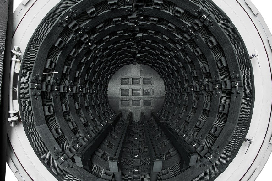
A set of nozzles is distributed evenly around the hot zone, as well as at the front and at the rear. Hinged flaps close the nozzle during heating and are opened by the high velocity gas flow during quenching.
Optionally also a metal hot zone and square shapes of the hot zone are also available as per user request.
The front door of the hot zone is directly hinged to the thermic chamber. It is opened and closed independently from the door of the vacuum chamber and can therefore guarantee the required tightness, for improved temperature uniformity within the work zone, and for reduced heat losses.
The heating system consists of a set of rings, made of wide band graphite rigid elements.
The heating power is distributed to three (3) independently controlled heating zones.
The hearth is made of high-grade isostatic graphite profiles. Molybdenum rods are mounted on the graphite supports to avoid direct contact between graphite and steel at high temperature.
The hot zone is easily accessible for the maintenance activities on the heating elements and on the thermal insulation.
Power Feed Through
Electric power is supplied to the heating elements through water cooled copper rods, assembled and sealed to the vacuum chamber.
The cooling water flow is continuously measured by digital flow meters that transmit the reading to the PLC to protect the system in case of lack of water.
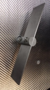
Convective Heating and Gas Circulation Fan
Convective heating is used to improve the heat transfer at low temperatures, when transfer by radiation in vacuum is less effective.
Protective gas is injected into the vacuum chamber after it has been evacuated to the required set value.
A gas circulation fan is installed on the front of the hot zone. The fan and its shaft are in CFC – Carbon Fiber Composite material.
The fan is driven by a water-cooled asynchronous electric motor installed on the front door of the hot zone.
Convective heating provides both faster heating and improved temperature uniformity within the working volume.
Temperature Sensors
Depending on the amount of heating zones control zones there will be one S-type Pt-PtRh thermocouple for each temperature control zone and one for over-temperature protection.
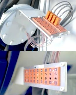
A feed-through for twelve (12) N-type charge thermocouples is installed.
The feed through is designed for 2 mm thermocouples.
SAT thermocouples can be inserted for temperature calibration, when needed.
Quenching System
The gas quenching system guarantees fast cooling of the charge (work-pieces) and of the hot zone. A centrifugal fan, installed at the rear of the furnace, circulates the protective cooling gas through the charge (work-pieces) and through a water-cooled copper fin tube heat exchanger, which is also installed behind the hot zone, between the fan and the internal shell of the vacuum chamber.
The cooling fan is connected to a three-phase water-cooled & vacuum sealed – asynchronous electric motor.
The motor casing is designed and manufactured to sustain a maximum pressure of 20 bar.
The motor is connected and sealed to the furnace vessel and no external sealing casing is needed.
The heat generated during the operation of the motor is removed by the high flow rate cooling water circulating in the water jacket of the motor casing. Bearing and sealing are also protected by cooling water. Additionally, the motor is provided with two sensors that measure the temperature of the stator winding and of the bearings. In case their reading reaches a value set in the PLC, the control system automatically reduces the quenching pressure, to protect the motor, and it eventually generates an alarm.
The motor can start under the condition of full vacuum inside the chamber, to shorten the quenching preparation time. The heat exchanger is designed to guarantee the most effective transfer of heat from the quenching gas to the cooling water supplied during the quenching step of the process. The cooling gas enters the hot zone through a set of nozzles, suitably distributed around the working volume, and it exits though hatches at the rear.
This configuration provides a fast and uniform cooling of the charge (work-pieces) and of the hot zone and it is particularly suited to the heat treatment of charge distributed along the whole useful length of the hot zone.
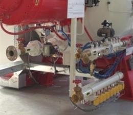
Cooling Water Distribution System
A cooling water distribution system assures adequate cooling of all furnace components. It is split into three independent loops:
- Circulation Loop 1: basic flow. This loop provides the amount of cooling water required for the operation during heating. Cooling water is distributed to the vacuum chamber, to the pumping group, to the current feed-through, etc. This circuit includes a high-pressure supply manifold and a return manifold, both in stainless steel. Flow interlock switches are installed on all critical return lines and ball valves on supply lines. The status of the interlocked circuits is displayed on the operator’s control panel.
- Circulation Loop 2: quenching flow. This loop provides the additional amount of cooling water required during the quenching of the charge (work-pieces). Water is supplied to the internal heat exchanger through an independent inlet manifold. This loop also includes a return manifold independent form the circulation loop 1, for the basic flow.
- Circulation Loop 3: oil diffusion pump flow. In case high vacuum is needed, then the furnace will be equipped with diffusion pump, which needs its own suitable temperature and cooling water required flow. Normally this circulation loop will be connected to a chiller.
Non-ferrous pipe fittings, and non-metallic hoses are used for all cooling circuits.
The high-pressure manifold includes a connection for the customer supplied emergency cooling water.
Automatic valves are provided to switch from facility water to emergency water upon loss of electricity.
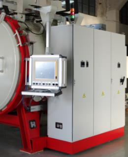
Electric Power and Process Control Enclosure
A freestanding power distribution and process control enclosure is supplied
with the furnace.
The cabinet is located close to the furnace to reduce the footprint of the equipment. The system includes a support arm system to house the industrial PC.
An additional enclosure is mounted on the top of the furnace and it houses the transformers for the heating system and the thyristors for the control of the power supplied.
Inside the electric cabinet, motor starters and circuit breakers are provided for the electrical motors. Circuit breaker disconnects are provided for other circuits. Lockable disconnects on the face of the cabinet, or strategically placed lockable local disconnects, are provided for maintenance to minimize downtime but ensure safety.
The power distribution & process control enclosure has a single electrical
power connection and provides power to the furnace components. The customers is responsible for the connection of the power supply. The cable can be lead in the cabinet from top or bottom, depends on customer’s requirement.
The cabinet houses the following instrumentation and components:
- PLC Siemens
- Industrial PC, with 19” HMI
- Eurotherm temperature controller
- Eurotherm over-temperature protection instrument
- Main switch breaker
- Power meter
- Analogue ammeters to measure the current in the heating elements.
- UPS – uninterrupted power supply
- Andon light (green, yellow & red)
- Acoustic alarm device
- Set of internal safety lights
- Fresh air intake fan
The heating power supplied to the heating elements is controlled through a thyristor.
Temperature Control System
The system allows different control modes, depending on the specific process requirements and applications.
- Master thermocouple control. In this control mode, the actual temperatures measured by the furnace thermocouples within the hot zone are used by the PLC to compute the set temperature required by the cycle programmed. The set value is transmitted to the temperature controllers, which calculate the output signal to the thyristors, in accordance with the PID parameters set.
- Charge thermocouple control. Various processes require the furnace temperature to be controlled with the charge thermocouples; this is for example the case of large and heavy steel moulds. The charge thermocouple is typically placed in a suitable position inside the charge (work-pieces) and the program is allowed to enter the next segment only when the value measured reaches the set value.
- Isothermal quench. Isothermal quench is a control mode useful when heat treating large and heavy parts and/or parts with a complex shape. The control system measures the temperature on the surface and at the core of the part. The cooling is set on hold when the difference in temperature between surface and core is above a set value. When the required value is reached, cooling of the charge (work-pieces) is allowed to continue. This control mode is useful to prevent cracking during heat treatment, and to minimize distortion of the parts.
Safeties and Protections
The furnace is designed and manufactured in compliance with the relevant health and safety standards. The furnace control system is designed with safety interlocks that protect the equipment operators from injury and that
prevent damage to the furnace equipment during normal operation of the furnace.
The interlock and safeties include, among others:
- Vacuum interlock – in case the pressure inside the vacuum chamber exceeds the set value, the system automatically interrupts the heating. If the pressure is back to a value within the set, heating can continue.
- In case of failure of a control thermocouple, the PLC stops the heating and provides an alarm.
- In case of over-temperature within the hot zone, the over-temperature instrument stops the heating and the system provides an alarm.
- In case of lack of electrical power, the vacuum valve shuts down to a safe position.
- In case of lack of cooling water flow within the distribution system, the PLC stops the heating of the furnace and an alarm is provided.
The furnace door can only be opened when the pressure inside the vacuum chamber is balanced to the atmospheric pressure.
The furnace is provided with a safety relief valve, which opens in case the pressure inside the chamber exceeds the value of calibration.
Operating sound levels of individual components (ex. vacuum pumps, power supply, etc.) are less than 85dB for the majority of operation. However, sound levels may reach up to 90dB under load or the cumulative effect of multiple components for short periods of time (for example during gas backfill).