Beginning and Evolution of Vacuum Gas Quenching
Before the introduction of high pressure gas quenching, only some hot-work steels and a few other tool steels of small cross-section could be hardened satisfactorily inside a vacuum furnace.
Then, in 1975 IPSEN introduced the first single chamber vacuum furnace with gas quench. This furnace adopted a high-power two-speed turbine fan, enabling a charging pressure of 0.5 MPa, and also included a heat exchanger and a flow guide for optimizing the flow rate and turbulence for optimal quenching uniformity.
Since then a lot of optimizations by various vacuum furnace makers to the overall cooling system were made and nowadays, almost all cold-work, hot-work and high-speed steels can be vacuum hardened successfully using high-pressure gas quenching up to 2 MPa or 20 bars.
For vacuum heat treatment of low-alloy steels that require even better quench performance multi chamber vacuum furnaces are available which can be configured with separate chambers for either higher pressure gas quench or oil quench. That is of course more expensive to acquire and operate and in case of oil quench requires additional equipment like washing machines to clean the parts which come out of the oil bath.
Why is Vacuum Gas Quenching so Popular?
Heat treatments in salt baths and atmosphere furnaces are being replaced increasingly by processing in vacuum furnaces with high-pressure gas quenching, for a variety of reasons:
- Vacuum heat treatment guarantees perfect surface protection, eliminating the risk of decarburization and oxidation. Surface roughness and distortion can be virtually eliminated, thereby reducing finishing costs which can be very significant, especially as the work-piece after heat treatment is normally hard on the surface and thus very difficult to machine.
- Degassing of surfaces and perfect vacuum conditions produce better toughness at similar hardness levels and give longer life.
- Reliable process data acquisition and reproducibility, through automatic heat treatment and accurate control of all critical factors, ensures consistent and repeatable result.
- Special possibilities include combined brazing and hardening in a single operation, as well as safe annealing treatments, without decarburization, of used tools for refinishing purposes.
- Ideal working conditions with no uncomfortable heat, no environmental pollution and no effluent problems.
- Pre-programmed automatic processing, instant readiness of the installation and flexible operation result in significant savings in labor costs.
As a result vacuum gas quench or fall back to vacuum oil quench creates an even better result than previous salt or oil bath quench methods under atmosphere.
Available Cooling Methods inside a Vacuum Furnace
Once the heat treatment inside a vacuum furnace is done there are three methods to cool the work piece down:
- Vacuum Cooling – Considered the slowest method of cooling, it involves heat being removed from the furnace while the vacuum valves remain open. The furnace then cools down without backfill gas or using the recirculating fan. This method also relies on the specific heat loss potential of the hot zone for cooling. From 1350°C it will take about 14 hours to reach ambient temperature.
- Static Cooling – Using this method, the vacuum valves close and the furnace backfills with inert gas to a predetermined pressure, but maximum to the design capabilities of the furnace. The backfill valve will open and close to maintain the desired pressure level in the furnace during the cooling cycle. This mode of cooling does not use the recirculating fan, but the increased presence of inert gas negates the insulation characteristics of the hot zone, which significantly increases the cooling rate through convective heat loss. From 1350°C it will take about half time of vacuum cooling to reach ambient temperature.
- Forced Cooling – It starts with the vacuum valves closing and the furnace backfilling with inert gas to a predetermined level (negative or positive). Once the furnace reaches -16kPa (and pressure continues to rise until the specific set point is reached), the recirculating fan comes on to cool the charge (work-pieces) and the furnace by moving the hot gas across a water-cooled heat exchanger. Like static cooling, the backfill valve will open and close to maintain the desired pressure level in the furnace during the cooling cycle. This is the fastest method and will cool the furnace from 1350°C to ambient in about 2 hours.
How to Increase the Rate of Heat Removal
Increase the mass flow of the gas (velocity)
When IPSEN back in 1970s implemented high pressure quenching inside the vacuum furnace, then significant effect of pressure on heat removal was realized. So the higher the gas pressure, the more heat is being removed. The trick is that inside a single chamber, that is used for heating and quenching, the gas pressure can only be increased that much without damaging the hot zone. So if gas pressure is to be further increased then the gas quench operation has to be moved to a separate chamber that is designed only for high pressure gas quench or oil quench for that matter. Hence multi chamber vacuum furnace was born.
The effect of blower capacity on cooling rate
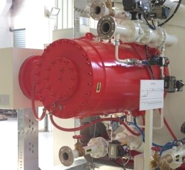
A quench blower consists of a motor-driven turbine wheel sealed within a vacuum-tight enclosure. The blower’s capacity is governed by the size of the wheel, the speed it can turn and whether the speed can be varied during the quench cycle.
Therefore, nowadays premium gas quench furnaces have frequency converters, variable speed motors and ability to start the fan under vacuum to shorten the quenching preparation time.
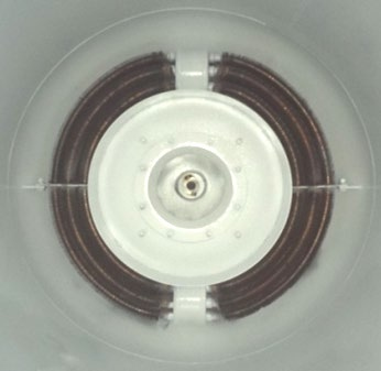
The effect of heat exchanger efficiency on the cooling rate
Premium high performance gas quench furnaces use water-cooled copper tube fin design. It does cost more, but it is more effective than steel or aluminum at heat transfer.
The effect of quenched gas composition on the cooling rate
The optimum quench gas will have a low density to minimize the amount of power required to blow it through the quench loop. It will also have a high specific heat, which can be considered as a measure of its capacity for heat removal from the charge (work-pieces). It must also be non-reactive with the materials that it is used to cool.
Based on availability, density and specific heat properties, hydrogen would appear to be good choice as a quenchant. However, because of the explosive risks associated with hydrogen, it is seldom used as a quench gas in commercial heat treating. Nitrogen is the most popular choice, primarily because it is readily available and inexpensive. It is similar quench effect at about 20 bar pressure as oil. Argon is used in some special applications but does not quench as effectively as nitrogen and is considerably more expensive. Helium also has excellent properties as a quench gas; it is used relatively frequently, especially for materials that have borderline hardenability in gas quenching.
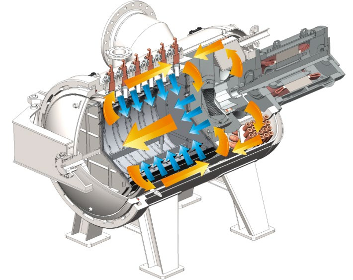
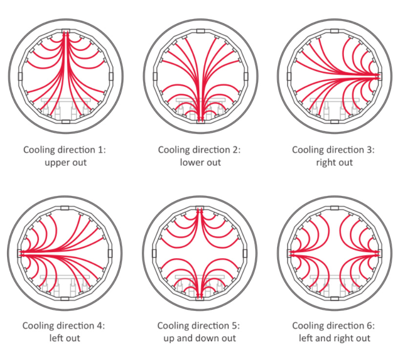
The effect of vacuum chamber design and charge (work-pieces) distribution on the cooling rate
It is well known fact, proven through field trials and computer modeling studies, that the flow patterns of quench gas through the charge (work-pieces) and vacuum chamber can have a significant effect on how quickly the charge (work-pieces) will cool. This effect exists regardless of quench pressure, blower size or any of the other factors already discussed. Consider that there is significant reduction of gas velocity only after 50 cm once it leaves the nozzle. Hence nozzle placement and gas quench direction can greatly impact whether your single chamber vacuum furnace can achieve needed gas quench performance or not.
Vacuum Gas Quench Speed Benchmarks
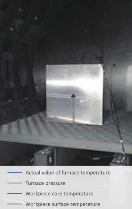
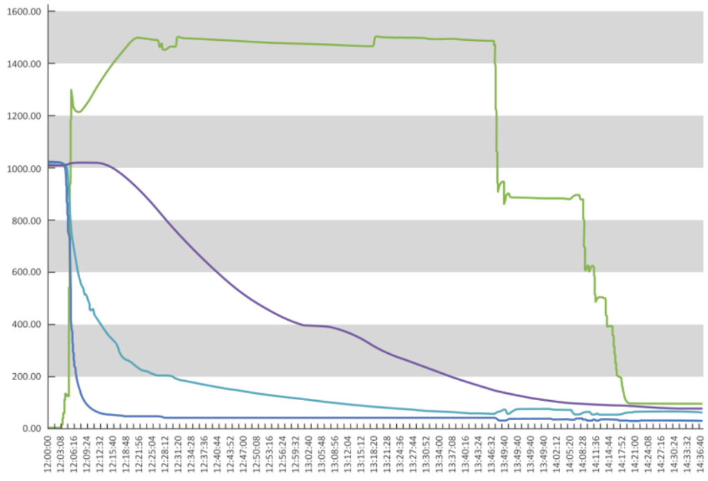
Cooling test of our premium vacuum gas quenching furnace at 15 bar gas pressure (N2) with sample material H13 500 kg (400 x 400 x 400mm):
Cooling range: 1020 °C to 540 °C
Cooling rate at the surface: 96 °C/min
Cooling rate at core: 11.4 °C/min
Cooling range: 400 °C to 250 °C
Cooling rate at the surface: 18.8 °C/min
Cooling rate at core: 5.5 °C/min
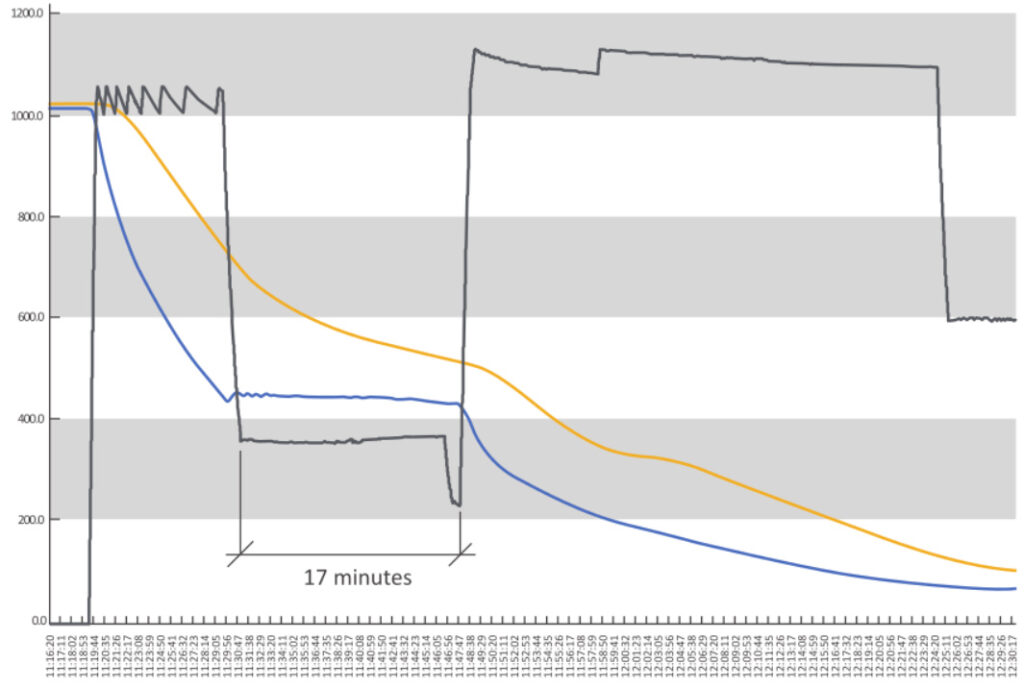
Isotherm quenching test. Cool down to a 400 °C, then soak to let the core temperature catch up with surface temperature. Modern control systems allow full control of the quench cycle.
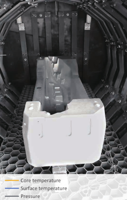
Isothermal starting temperature: 400 °C
Isothermal end condition: core and surface temperature difference of 100 °C
Surface temperature fluctuation < 20 °C
Isothermal end time: 17 minutes