 Русский
Vacuum Nitriding Furnace Overview
Our best seller vacuum furnace for nitriding is a pre-evacuated retort furnace that offers an excellent solution for a wide range of processes and applications.
It has a horizontal cubic heating zone and can be heated by convection with
protective gas, an advanced furnace control system that enables automatic supervision and therefore stable, economical and efficient controlled nitriding heat treatment, and precise control of nitriding layer on the workpieces.
The retort / hotzone can can operate in fine vacuum up to 850 °C Degrees.
The equipment can also be used for nitrocarburizing, pre-oxidation, post-oxidation, tempering and other heat treatments.
The system includes the following components:
- Hot zone
- Retort
- Vacuum system
- Nitriding and Nitrocarburizing Module (optional)
- Direct gas circulation and cooling system (optional)
- Indirect cooling system (retort & insulation)
- Process Gas Mixing Panel
- Electric Power and Process Control Enclosure
The nitriding vacuum retort furnace operates with high temperature uniformity and guarantees high quality, accurate and repeatable heat treatment processes.
Vacuum Nitriding Furnace Structural Design
Hot Zone
The cuboidal hot zone consists of a painted carbon steel casing that supports the ceramic fiber blanket thermal insulation assembly. Iron-chromium-aluminum ribbon heating elements are installed at both the sides of the hot zone, evenly distributed on the internal surface of the insulation.
During the cooling step of the process, openings at the bottom and at the top allow air circulation through the heating elements and between the insulation and the retort.
The furnace casing is welded on four support feet, so it can be placed on the factory floor.
Rails for a loading cart are located in between the legs.
Retort
The retort is horizontal, with circular section, and it is made in AISI 304 Stainless Steel.
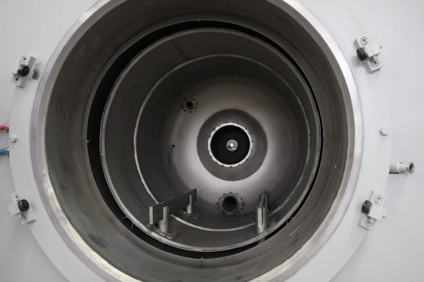
The front door is insulated and it is provided with a water-cooled lip seal.
The door opens from right to left as it affixed to an arm that connects it to a hinge mounted on the casing of the hot zone.
The locking of the door to the retort body is with a bayonet closure mechanism. The door is locked by an electric actuator.
Inside the retort, two rigid bars in AISI 304, supported by pins evenly distributed along the length of the working zone, provide a flat support to the charge (work-pieces).
Vacuum System
The vacuum pumping system is designed to fine vacuum criteria and consists of the following components and features:
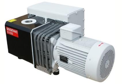
Rotary Vane Pump (s) – Leybold SV 200
Valves are pneumatically activated and motion controlled by limit switches.
Over-pressure safety valves are installed.
Leak detection port on the vacuum piping, for convenient maintenance operations and leak detection is available.
Vacuum gauge – the vacuum chamber is provided with a Pirani gauge. Vacuum levels are digitally displayed on the HMI.
The rotary vane pump is isolated from the piping system by bellows-type flexible couplings. These connectors minimize vibrations from reaching the furnace chamber.
The over-pressure protection is installed between the furnace and vacuum pumps. The vacuum system is interlocked to provide for safe operating conditions. The control system interlocks are designed to “fail-safe” in case of an electrical power failure.
Nitriding and Nitrocarburizing Module
The process gas supply system includes the following components:
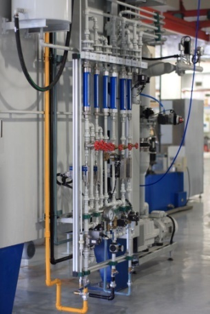
- One ammonia dissociator
- One hydrogen probe
- One burner
- One rapid pneumatic solenoid valve for safety flushing of the retort with nitrogen
- Flow-meters, valves, pressure switches, pressure gauges & piping
The dissociator – ammonia cracker – separates ammonia into its two constituent components: nitrogen and hydrogen. Ammonia flows through a heated tube that contains a catalyst, and the resulting mixture of gases is then introduced into the retort.
A dedicated probe continuously measures the content of hydrogen inside the retort and provides an output signal to the control system for this to calculate the nitrogen potential kn, adjust the flow of ammonia through the dissociator and recalibrate the most suitable process gas mixture for the programmed nitriding process.
The process gas is discharged from the retort into the room after flowing through a filter and though the dissociator into a combustion system, which is installed at the rear of the furnace.
In case of alarm, the retort is rapidly flushed with nitrogen, so that the furnace remains in safe conditions.
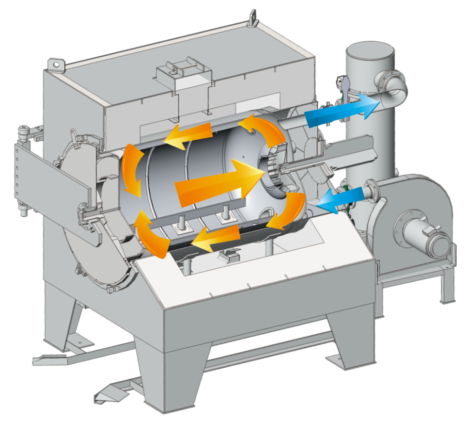
Direct Gas Circulation and Cooling System
An optional gas circulation system guarantees an effective heat transfer of the heat from the retort to the charge (work-pieces) and a uniform distribution of the temperature throughout the entire working volume.
The system includes a fan and a flow distribution cylinder, both in AISI 304.
The fan motor is water cooled, vacuum-tight and it is directly flanged to the retort, therefore no dynamic seal is required for the shaft that connects the motor to the fan.
The flow distribution cylinder ensures an even circulation of the process gas inside the hot zone and through the charge (work-pieces), to provide increased heat transfer and to guarantee high temperature uniformity.
A direct gas cooling system is available as an option. It includes a high throughput blower, a heat exchanger and a vacuum tight shell.
During the cooling phase, the hot process gas inside the retort is circulated out of the retort and through a heat exchanger, where it transfers heat to the water circulating in the secondary circuit.
The cooled process gas is then circulated back into the retort, where it removes the residual heat from the charge (work-pieces), for an increased cooling speed and a reduced cycle time.
Indirect Cooling System
A blower is installed at the bottom of the furnace casing. Cold air from the ambient is forced through the gap between the furnace insulation inside wall and the retort, and it is exhausted at the top of the furnace. The air is released into the workshop.
This system allows rapid cooling of both the retort and the ceramic fiber thermal insulation.
Electric Power and Process Control Enclosure
The power and control instrumentation are housed inside a freestanding power distribution and process control enclosure.
Inside the electric cabinet, motor starters and circuit breakers are installed for the electrical motors. Circuit breaker disconnects are installed for other circuits. Lockable disconnects on the face of the cabinet, or strategically placed lockable local disconnects, are provided for maintenance to minimize downtime but ensure safety.
The power distribution and process control enclosure has a single electrical
power connection and provides power to the furnace components. The cable can be lead in the cabinet from top or bottom, depends on customer’s requirement.
The cabinet houses the following instrumentation and components:
- PLC Siemens
- Industrial PC, with 19” HMI
- Eurotherm temperature controller
- Eurotherm over-temperature protection instrument
- Main switch breaker
- Power meter
- Analogue ammeters to measure the current in the heating elements.
- UPS – uninterrupted power supply
- Andon light (green, yellow & red)
- Acoustic alarm device
- Set of internal safety lights
- Fresh air intake fan
Two type K thermocouples provide measurement signals to the temperature control instrumentation. One thermocouple is installed outside the retort and used for the control of the power to the heating elements, one thermocouple is installed inside the retort and it used for temperature control, record and to prevent over-heating.
The heating power supplied to the heating elements is controlled through a thyristor.
A vacuum gauge provides the measurement signal to the PLC. The vacuum levels are displayed on the HMI.
Safeties and Protections
The furnace is designed and manufactured in compliance with the relevant health and safety standards. The furnace control system is designed with safety interlocks that protect the equipment operators from injury and that
prevent damage to the furnace equipment during normal operation of the furnace.
The interlock and safeties include, among others:
- In case of failure of a control thermocouple, the PLC stops the heating and provides an alarm.
- In case of over-temperature within the hot zone, the over-temperature instrument stops the heating and the system provides an alarm.
- In case of lack of electrical power, the vacuum valve shuts down to a safe position.
- In case of lack of cooling water flow within the distribution system, the PLC stops the heating of the furnace and an alarm is provided.
The furnace door can only be opened when the pressure inside the vacuum chamber is balanced to the atmospheric pressure.
Showcase: Nitriding Results

35CrMoV Nitriding
Nitride layer depth 0.75mm
Surface hardness 640HV1
Core hardness 333HV1
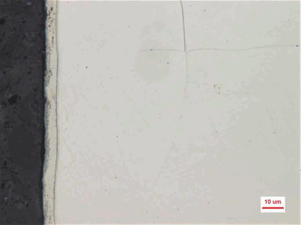
304 Nitriding
The nitriding depth ~ 5.2μm
Surface hardness 710HV0.05
Core hardness 250HV0.3

38CrMoAl Material nitriding
No compound layer
Surface hardness is ~ 970HV1
The nitriding depth 0.42mm

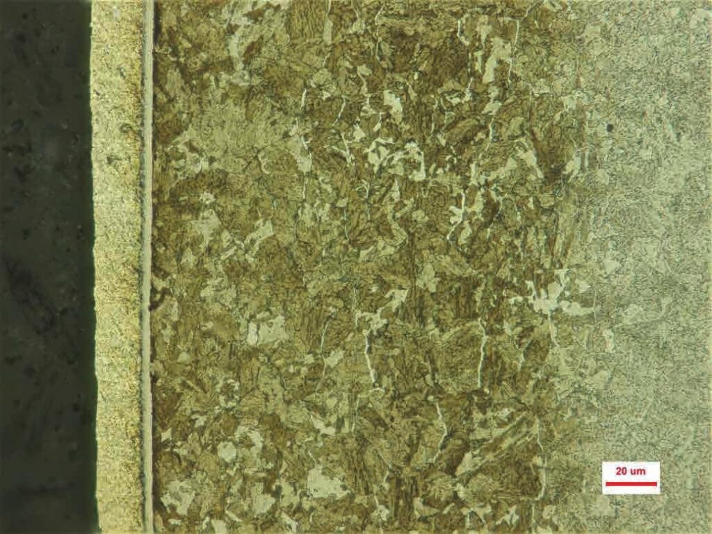
H13 Nitriding
The white layer shown on the picture is the aluminum foil
No compound layer
Surface hardness is ~ 940HV1
The nitriding depth 0.32mm
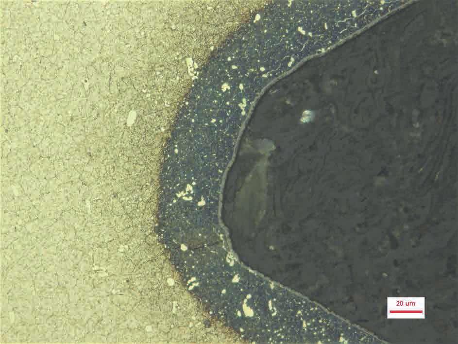
DC53 Nitriding
Post oxide layer 1.8μm
Core hardness 760HV0.3
Surface hardness is ~ 1072HV0.1
The nitriding depth 0.12mm
25Cr3Mo Nitridation
Compound layer depth 2.9μm
Core hardness 237HV0.3
Surface hardness ~ 842HV0.1
The nitriding depth ~ 0.30mm